Over the past few years, the PCB industry has been moving into a new reality.
Designs are no longer just about connecting components — they are about enabling performance, density, and reliability at levels that simply didn’t exist before.
From an engineering standpoint, routing density today is driven as much by electrical performance as by physical space.
As data rates increase and packaging becomes tighter, the PCB increasingly influences system-level performance rather than serving only as an interconnect.
This is exactly where technologies like mSAP come into play.
What is mSAP – and why does it matter?
mSAP stands for Modified Semi-Additive Process.
It enables the production of extremely fine copper features that are difficult or impossible to achieve using conventional subtractive etching.
With traditional etching, once trace widths shrink below a certain threshold, copper undercut becomes very hard to control.
At that point, geometry accuracy directly impacts impedance control, signal loss, and manufacturing yield.
How mSAP Works
mSAP typically starts with a copper seed layer only a few microns thick.
Imaging defines the desired trace geometry, followed by selective copper plating.
The remaining thin copper layer is then removed with a controlled flash etch.
Because only minimal copper is etched, trace definition is significantly sharper compared to standard processes.
Technical Comparison of PCB Fabrication Processes
The table below summarizes the practical differences between common PCB fabrication approaches, including both conventional multilayer boards and HDI-based subtractive processes.
| Parameter | Subtractive PCB mSAP (incl. HDI) | mSAP | SAP |
|---|---|---|---|
| Typical Line / Space | ~50 – 100 µm | ~20 – 40 µm | ~5 – 20 µm |
| Copper Start Thickness | Thick copper foil | Thin copper seed layer | Ultra-thin copper seed layer |
| Process Complexity | Low–Medium | Medium–High | Alto |
| Typical Applications | Standard PCBs and HDI | Advanced HDI designs, substrate-like and interposer applications | IC substrates, ultra-fine pitch |

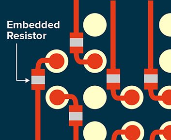
Trace Geometry Comparison – Subtractive vs. mSAP
Note: While full SAP is typically required for advanced IC substrates with ultra-fine geometries, mSAP is increasingly used in substrate-like and interposer applications, particularly where line/space requirements are in the 20–25 µm range. In these cases, mSAP provides a practical balance between performance, manufacturability, and cost.
In this context, “substrate-like” refers to advanced PCB structures that approach substrate-level routing density and electrical performance, without requiring the ultra-fine geometries and full process complexity of true IC substrates.
Practical Considerations
While mSAP enables finer geometries beyond standard subtractive processes, it also introduces additional process sensitivities.
Key considerations include tighter control of the copper seed layer, precise imaging and plating uniformity, and careful flash-etch tuning.
As with any fine-line process, yield and consistency depend heavily on equipment capability and process discipline.
mSAP at Fineline Global
At Fineline Global, we have already supported and manufactured advanced PCB builds using mSAP processes. In several recent projects, conventional HDI approaches could not meet the required line/space constraints. mSAP enabled higher routing density while maintaining electrical performance and production stability.
Looking Forward
As electronic systems continue to demand higher density and tighter tolerances, additive and semi-additive processes will become increasingly standard. From our perspective, mSAP represents a practical and scalable step forward for next-generation PCB manufacturing.

Written by Maysa Salameh, CTO, Fineline Global